


72 www.xilinx.com Ethernet 1000BASE-X PCS/PMA or SGMII v9.1
UG155 March 24, 2008
Chapter 6: The Ten-Bit Interface
R
Spartan-3, Spartan-3E and Spartan-3A Devices
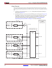
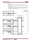
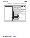
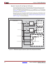
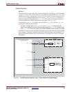
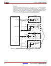
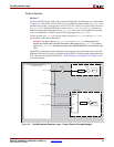
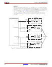
The logic described previously for Virtex-II and Virtex-II Pro devices does not meet the
input setup and hold requirements for TBI with Spartan-3, Spartan-3E and Spartan-3A
devices. A DCM must be used on both the pma_rx_clk0 and pma_rx_clk1 clock paths
(see Figure 6-3). This is performed by the example design delivered with the core (all signal
names and logic match Figure 6-3).
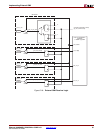
Phase shifting may then be applied to the DCM to fine-tune the setup and hold times at the
TBI IOB input flip-flops. Fixed phase shift is applied to the DCM using constraints in the
example UCF for the example design. See “Constraints When Implementing an External
GMII” in Chapter 12 for more information.
Figure 6-3: TBI Receiver Logic for Spartan-3, Spartan-3E, and Spartan-3A Devices
component_name
_block (Block Level from example design)
pma_rx_clk0
IBUFG
IOB LOGIC
IPAD
rx_code_group[0]
IBUF
IPAD
rx_code_group_ibuf[0]
D
Q
Ethernet 1000BASE-X PCS/PMA
or SGMII LogiCORE
pma_rx_clk0
BUFG
IOB LOGIC
D
Q
pma_rx_clk1
IBUFG
IOB LOGIC
IPAD
BUFG
pma_rx_clk1
rx_code_group0[0]
rx_code_group1[0]
rx_code_group1_reg[0]
rx_code_group0_reg[0]
DCM
CLKIN
CLK0
FB
DCM
CLKIN
CLK0
FB
pma_rx_clk0_bufg
(62.5 MHz)
pma_rx_clk1_bufg
(62.5 MHz)