


198 www.xilinx.com Ethernet 1000BASE-X PCS/PMA or SGMII v9.1
UG155 March 24, 2008
Chapter 14: Special Design Considerations
R
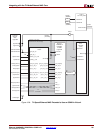
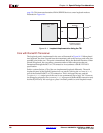
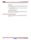
page 38). This instructs the attached PMA SERDES device to enter loopback mode as
illustrated in Figure 14-1.
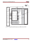
Core with RocketIO Transceiver
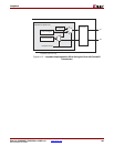
The loopback path is implemented in the core as illustrated in Figure 14-2. When placed
into loopback, the data is routed from the transmitter path to the receiver path at the last
possible point in the core. This point is immediately before the RocketIO interface. When
placed in loopback, the core creates a constant stream of Idle code groups that are
transmitted through the MGT or GTP transceiver in accordance with the IEEE 802.3
specification.
Earlier versions (before v5.0) of the core implemented loopback differently. The serial
loopback feature of the RocketIO transceiver was used by driving the LOOPBACK[1:0]
port of the RocketIO (MGT or GTP) transceiver. This is no longer the case, and the
loopback[1:0] output port of the core is now permanently set to logic “00.” However,
for debugging purposes, the LOOPBACK[1:0] input port of the RocketIO transceiver may
be directly driven by the user logic to place it in either parallel or serial loopback mode.
Figure 14-1: Loopback Implementation Using the TBI
Ethernet 1000BASE-X
PCS/PMA or SGMII
Core
1000BASE-X PMA
SERDES
Tx
Rx
TBI
FPGA
Loopback occurs in
external SERDES