


Ethernet 1000BASE-X PCS/PMA or SGMII v9.1 www.xilinx.com 35
UG155 March 24, 2008
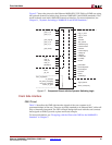
Core Interfaces
R
Configuration Vector (Optional)
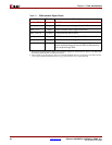
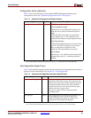
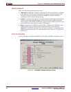
Table 2-4 shows the alternative to the optional MDIO Management Interface, the
configuration vector. See “Optional Configuration Vector” in Chapter 9.
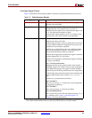
Auto-Negotiation Signal Pinout
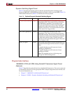
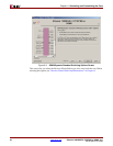
Table 2-5 describes the signals present when the optional Auto-Negotiation functionality is
present. For more information, see Chapter 10, “Auto-Negotiation.”
Table 2-4: Optional Configuration and Status Vectors
Signal Direction Description
configuration_vector[3:0]
1
1. This signal is synchronous to the core’s internal 125 MHz reference clock. This is userclk2 when the
core is used with the RocketIO transceiver; this is gtx_clk when the core is used with TBI.
Input Bit[0]: Reserved (currently unused)
Bit[1]: Loopback Control
• When the core with RocketIO transceiver is
used, the core is placed in internal loopback
mode.
• With the TBI version, Bit 1 is connected to
ewrap. When set to ‘1,’ this indicates to the
external PMA module to enter loopback mode.
Bit[2]: Power Down
• When the RocketIO transceiver is used (when
set to ‘1’), the MGT is placed in a low power
state. A reset must be applied to clear.
• With the TBI version this bit is unused.
Bit[3]: Isolate
When set to ‘1,’ the GMII should be electrically
isolated. When set to ‘0,’ normal operation is
enabled.
Table 2-5: Optional Auto-Negotiation Interface Signal Pinout
Signal Direction Description
link_timer_value[8:0]
1
1. These signals are synchronous to the core’s internal 125 MHz reference clock. This is userclk2 when the
core is used with the RocketIO transceiver; this is gtx_clk when the core is used with TBI.
Input Used to configure the duration of the Auto-
Negotiation Link Timer period. The duration of this
timer is set to the binary number input into this port
multiplied by 4096 clock periods of the 125 MHz
reference clock (8 ns). It is expected that this signal
will be tied off to a logical value.
This port is replaced when using the dynamic
switching mode.
an_interrupt
1
Output Active high interrupt to signal the completion of an
Auto-Negotiation cycle. This interrupt can be
enabled/disabled and cleared by writing to the
appropriate PCS Management Register.