


62 www.xilinx.com Ethernet 1000BASE-X PCS/PMA or SGMII v9.1
UG155 March 24, 2008
Chapter 5: Using the Client-side GMII Data Path
R
Virtex-II Pro and Virtex-II Devices
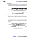
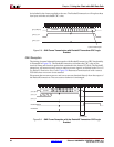
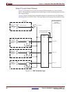
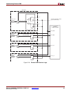
Figure 5-14 illustrates how to create an external GMII transmitter in a Virtex-II family
device. The signal names and logic shown on the figure exactly match those delivered with
the example design.
Figure 5-14 shows that the input transmitter signals are registered in device IOBs before
presenting them to the FPGA fabric. This logic achieves the required setup and hold times.
Figure 5-14: GMII Transmitter Logic
gmii_tx_clk
IBUFG
IOB LOGIC
IPAD
gmii_tx_clk_ibufg
gmii_txd[0]
IBUF
gmii_txd_ibuf[0]
D
Q
gmii_tx_en
gmii_tx_en_ibuf
gmii_tx_er
gmii_tx_er_ibuf
gmii_txd[0]
gmii_tx_en
gmii_tx_er
BUFG
Ethernet 1000BASE-X
PCS/PMA
or SGMII LogiCORE
IPAD
IPAD
IPAD
IBUF
IBUF
D
Q
D
Q
gmii_tx_clk_bufg
gmii_txd_int[0]
gmii_tx_en_int
gmii_tx_er_int
Transmitter
Elastic
Buffer
userclk2 (if RocketIO is used)
gtx_clk (if TBI is used)