


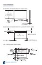

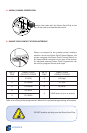


A • MEDIA LOADING ORIENTATION
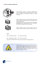
Position the cards with the Smart Card Chip at the
top of the card and towards the printer.
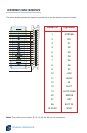
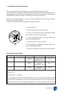
B • SMART CARD CONTACT STATION INTERFACE
When a command to the parallel printer interface
sends a card to the Smart Card Contact Station, the
printer connects the Smart Card Contact Station to
the female DB-9 connector on the rear of the printer.
An attached external Smart Card Programmer can
be used to program Smart card chips
Refer to the Card printer programmer’s Manual for complete programming information.
DO NOT position printing over the Smart Card Chip.
APPENDIX B
48
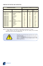
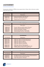
DB - 9 SMART CARD DB - 9 SMART CARD
PINS CONTACT POINTS PINS CONTACT POINTS
1 CI (VCC) 6 C6 (Vpp)
2 C2 (Reset) 7 C7 (I/O)
3 C3 (Clock) 8 C8 (RFU)
4 C4 (RFU)
5 C5 (GND)
9 (GND when chip is at station)