


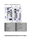


6. Isolation Transformer 13. Isolation Transformers
7. Power Supply 14. 4 Port PHY
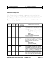
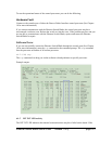
Hardware Subsystem
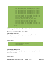
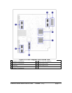
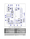
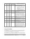
In the following tables, refer to the identified component-area numbers on indicated in the
pictures in the proceeding section. The indications of malfunction may be identified either during
normal operation, or in response to a specific test. The various tests that may be initiated are
shown in subsequent sections.
The information is equally applicable to both the Base Interface and the Fabric Interface switch
subsystems unless otherwise noted.
Base ZMC 0
#
ZMC 1
#
Hardware
Subsystem
Indications of Malfunction
4 3 CPU
A CPU failure may be indicated by any of the
following:
• A failure to run the Power-On-Self-
Test (POST)
• A failure to boot the OpenArchitect
kernel
• Kernel panics
Loss of CPU response sometime after
operation is initiated
5 3
RAM The Ethernet Switch Blade uses SDRAM for
the primary CPU memory system. A failure of
RAM will generally cause any of the
following:
• Kernel panics
• Loss of CPU response
• Unexplained software failures
1 8
ROM The Flash ROM subsystem on the Ethernet
Switch Blade is used only on boot-up. The
contents are decompressed and copied to RAM
memory for further use. A ROM failure will
generally cause a failure in the boot process.
9, 10 6, 7
Switch Fabric The Ethernet Switch Blade has four switch
fabric chips: 2 for the Base Interface with 24
ports, and 2 for the Fabric Interface with 48
ports. A Switch Fabric failure may result in
Ethernet Switch Blade User's Guide release 3.2.2j page 176