


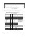
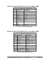

Structure of Standard IPMI Commands: From BMC to PMC
Structure of Standard IPMI Commands BMC - PMC
Byte Data Field Description
1 rsAddr <slot’s IPMB addr>
2 netFn/Lun <netFn>
3 check1 <chksm1>
4 rqAddr <sw_id>
5 seq no <seq>
6 command <cmd>
7 optional data byte <arg1>
7+x optional data
bytes
<argN>
7+x+1 check2 <chksm2>
Table C.5: Standard IPMI Commands
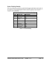
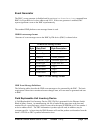
Structure of Standard IPMI Responses: From PMC to BMC
Structure of Standard IPMI Responses PMC - BMC
Byte Data Field Description
1 rqAddr <sw_id>
2 netFn/Lun <netFn>
3 check1 <chksm1>
4 rsAddr <slot’s IPMB addr>
5 seq no <seq>
6 command <cmd>
7 completion code <ccode>
8 optional data byte <arg1>
8+x optional data bytes <argN>
8+x+1 check2 <chksm2>
Table C.6: Standard IPMI Responses
Ethernet Switch Blade User's Guide release 3.2.2j page 352