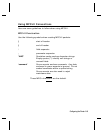
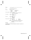
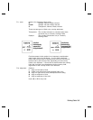
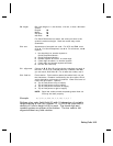
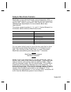
G3. action The action to perform to the graphic. Options:
A Add the graphic.
C Clear the graphic from the printer.
G4. device Graphic storage device:
R Volatile RAM (format must contain a graphic field)
T Temporary Storage
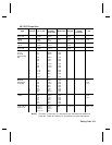
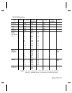
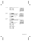
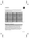
G5. units Unit of measure. Options:
E English, measured in 1/100 inches
M Metric, measured in 1/10 mm
G Graphic, measured in dots. For bitmapped graphics, use G.
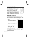
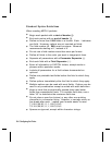
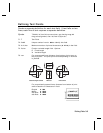
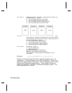
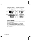
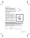
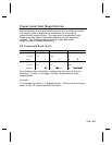
G6. row Distance between the bottom of the graphic image area and
the first bitmap line. This is usually 0, unless you want a fixed
amount of white space around the graphic image. See
"Positioning the Graphic Image," for more information.
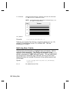
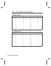
English 0 - 999
Metric 0 - 2539
203 Dots 0 - 2029
300 Dots 0 - 2699
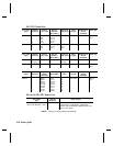
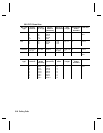
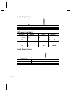
G7. column Distance between the left edge of the graphic image area and
the left edge of first bitmap line. This is usually 0, unless you
want a fixed amount of white space around the graphic image.
See "Positioning the Graphic Image," for more information.
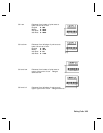
English 0 - 399
Metric 0 - 1015
203 Dots 0 - 811
300 Dots 0 - 1199
G8. mode Imaging mode. Enter 0.
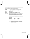
G9. "name" Graphic name (optional), 0-8 characters, enclose within
quotation marks.
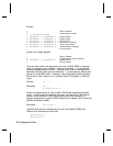
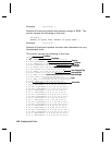
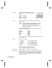
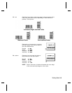
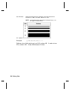
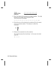
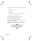
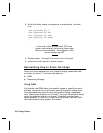
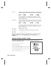
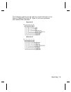
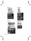
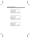
Example
{G,99,A,R,G,0,0,0,"99Wire"
p
Adds a graphic image identified by number 99 to volatile RAM.
The graphic uses dot measurement. The image will be placed
according to the row and column parameters in the graphic field.
The imaging mode is 0 and the image is called 99Wire.
5-12
Creating Graphics