


2-4 CHAPTER 2: INSTALLING THE SYSTEM
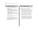
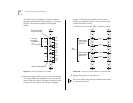
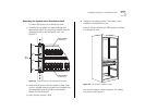
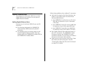
To find the top of the pattern, locate the midpoint
between any two holes that are spaced
1
/
2
inch apart.
Figure 2-3 shows the universal mounting hole
pattern.
Figure 2-3 Universal Mounting Hole Pattern
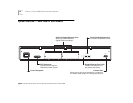
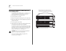
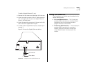
4 Determine which holes to use to mount your system.
Two Switch 3900s are designed to mount in any 3U
space of the rack (that is, the space occupied by three
instances of the universal mounting hole pattern).
Figure 2-4 illustrates the positions of two Switch
3900s, one attached to holes 1 and 4 and the other
attached to holes 6 and 9.
To mount only one Switch 3900, use either position.
Figure 2-4 Placement of Switch 3900s in a Distribution Rack
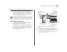
5 Repeat the process on the other rail.
Be sure to select holes that are parallel to each other
on the mounting rails.
Top of the pattern
or top of the rack
Universal
mounting
hole pattern
= 1U
= 1 3/4 inches
1/2"
1/2"
1/2"
1/2"
5/8"
5/8"
5/8"
5/8"
5/8"
5/8"
1U
1U
1U
Bottom of the pattern
Hole 1
Hole 3
Hole 6
Hole 8
Placement of
Switch 3900
(position 2)
Placement of
Switch 3900
(position 1)
3U
(5.25")