


System Checks 4-5
System Checks
After the system has successfully completed the
power-up diagnostics, check the items in Table 4-1 to
verify that the system is operating correctly. If you
discover abnormal conditions, see Chapter 6.
Next Step: Software Configuration
Your Switch 3900 system is shipped from the factory
with the software installed and IEEE 802.1d bridging
disabled. To configure your system for your particular
networking environment (including customized
filtering and setting up SNMP), you must first
establish management access. See Chapter 5.
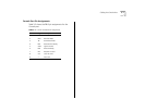
Table 4-1 System Power-Up Checklist
Check Description
Power-up
error messages
If there is a problem during power-up, the
messages are displayed in the Administration
Console connection through the Console port.
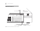
Normal LED
activity
When the power-up diagnostics are running,
the LEDs light in a certain pattern as described in
the “Power-up Diagnostics” section. After you
properly cable the system and the system
successfully completes the power-up diagnostics,
look for the following normal LED activity:
System:
Power LED = Green
Fault LED = Not lit
Each port:
Pckt status LED = Yellow
Stat status LED = Green
If an LED does not light or shows a color different
from the one indicated here, see Chapter 6 for
information about the cause of the problem.