


Front Panel Connections and LEDs 11
Front Panel
Connections and
LEDs
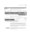
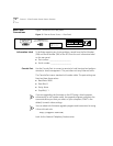
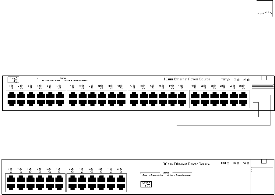
Figure 1 and Figure 2 show the front-panel details of the 24-port and
12-port EPS units. The LEDs are described in later in this section.
Figure 1 24-Port Ethernet Power Source — Front View
Figure 2 12-Port Ethernet Power Source — Front View
Both the 12-port (P/N 3C10220) and the 24-port (P/N 3C10222) versions
of the EPS have two rows of 10BASE-T/100BASE-TX ports. The input
ports, on the bottom row, are numbered from left to right (as you face
the front of the unit). Each output port is located immediately above the
input port to which it corresponds. You must use non crossover cables
with both input and output ports.
10/100BASE-TX
Data Input Ports
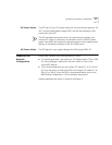
The EPS input ports (bottom row) accept Ethernet data only (Tx/Rx) over
the standard two wire pairs on an RJ-45 connector (Transmit on pins 1
and 2; Receive on pins 3 and 6).
Note: Bottom row connectors are input ports (data only).
Top row connectors are output ports (data and power).
Note: Bottom row connectors are input ports (data only).
Top row connectors are output ports (data and power).