


22 CHAPTER 2: INSTALLING THE ETHERNET POWER SOURCE AND END DEVICES
Power-up Sequence The following sections describe how to add power to your EPS and
prepare it for operation.
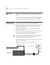
Adding Power To add power to the EPS, follow these steps.
CAUTION: The EPS has no On/Off switch; the only way to connect or
disconnect the power is to insert or remove the power cord from the unit.
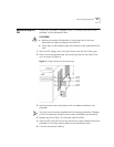
1 Insert the power cord that comes with the unit into the power socket on
the rear panel of the EPS.
2 Insert the other end of the power cord into the power outlet.
The EPS runs through a Power-On Self-Test (POST), which takes
approximately 10 seconds.
Verifying Correct
Operation
During the Power-On Self-Test, all ports on the EPS are disabled. The LEDs
light in this sequence:
■ All LEDs light for 2 seconds.
■ All LEDs turn off for 2 seconds.
■ AC power LED is continually lit.
■ All Port LEDs are ready with normal indications.
If you see other behavior in the LEDs, see “Solving EPS Problems” in
Chapter 3.
Selecting the Correct
Cables
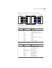
Each of the input ports (the lower row of RJ45 connectors) on the front of
the EPS are configured as “route through” ports; that is, all 4 data wires
(pins 1,2,3 and 6) connect directly to the same data wires on the output
port directly above it (in the upper row of RJ45 connectors).
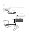
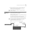
To make a connection to a powered MDI port, use a standard
straight-through cable, not a cross-over cable. The cable must include all
8 wires (4 pairs), as shown in Figure 7.