


12 CHAPTER 1: 3COM ETHERNET POWER SOURCE OVERVIEW
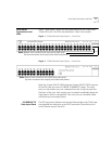
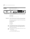
10/100BASE-TX
Data and Power
Output Ports
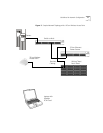
The EPS output ports (top row) carry two kinds of transmissions:
■ Ethernet data on the standard two wire pairs on an RJ-45 connector
(Transmit on pins 1 and 2; Receive on pins 3 and 6)
and
■ DC power on the previously unused wire pairs of the RJ-45 connector
(-24VDC Return on pins 4 and 5 and -24VDC on pins 7 and 8)
The maximum segment length from the switch or hub to the Network
Interface Card (NIC), including the EPS, is 100 m (328 ft.) using
Category 5 twisted pair cable.
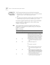
LEDs lists the lights (LEDs) on the front of the EPS and their states. For
information on using the LEDs for problem solving, see “Solving EPS
Problems” in Chapter 3.
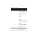
Table 3 LED Behavior
Per-port Status Indications
Visual Indications (for Each Port) Port Status
Yellow LED Green LED Note: Do not automatically assume that a
yellow LED indicates a problem. For example, if
the yellow LED for any port is ON, the EPS is
not supplying power to that port/device, which
may indicate that the device is not capable of
accepting power via its Ethernet connection.
Off On ■ Normal condition. Port power is turned on
and a device is drawing power from the
port.
Off Off ■ Main power supply is off.
or
■ Port power is turned off.
or
■ Both main power and port power are on,
but no device cable is plugged into the
port.
On Off ■ Either the device that is plugged into the
port is incapable of accepting power via its
Ethernet connection, or it has attempted to
draw too much power from the port. The
EPS has shut off the port power.
On On ■ An internal fault has occurred on this port.
The EPS has shut off the port power.