


24 CHAPTER 2: INSTALLING THE ETHERNET POWER SOURCE AND END DEVICES
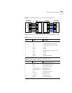
Power Splitter
Cable
The power splitter cable has a single RJ45 female connector on one end.
All eight pins on this connector are connected, either to the power or to
data.
On the other end, the cable is split into two portions. The power plug
carries the –24VDC (and returns) from pins 4, 5, 7, and 8. The RJ45
carries the data signals (transmit and receive) on pins 1, 2, 3, and 6.
Connecting an NBX
Business Telephone
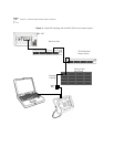
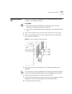
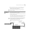
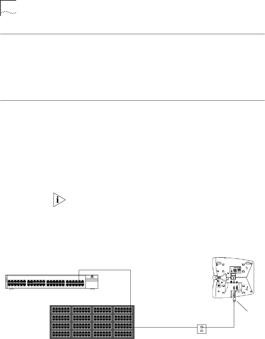
Figure 8 illustrates how to connect an NBX Business Telephone, using the
power splitter cable (3C10223: 12 pack). Follow these steps:
1 Before you attach any other cable to the female RJ45 connector on the
power splitter, insert the power splitter power plug into the power
receptacle on the telephone.
2 Plug the male RJ45 connector on the power splitter into the RJ45
receptacle on the telephone.
3 Using Category 5 cable that has been checked for continuity on all eight
wires, connect an EPS output port (a port on the upper row of
connectors) to the data jack closest to the telephone.
This connection may involve multiple segments such as the patch panel
and premises cabling shown in Figure 8. The total length of the
connection path should not exceed 100 meters.
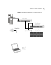
See Figure 4 in Chapter 1 for a sample topology using the EPS and the
NBX 100 Business Telephone.
Figure 8 Connecting the EPS to an NBX Business Telephone
Ethernet Power Source
Wiring Closet
Patch Panel
Premises
Cabling
NBX Telephone
Splitter
Wall
Jack