


28
C
HAPTER
2: I
NSTALLATION
AND
S
ETUP
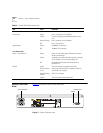
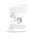
Stacking the Switch
and Other Devices
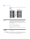
Up to four units can be placed on top of one another. If mixing
SuperStack II devices, the smaller units must be positioned at the top
using rubber pads.
This section relates only to physically placing the devices on top of each
other. The switch cannot be used to form a logical stack. It cannot be
linked to other switches using special expansion cables to form a larger
switch.
Apply the pads to the underside of the device by sticking a pad in the
marked area at each corner of the switch. Place the devices on top of
each other, ensuring that the pads of the upper device line up with the
recesses of the lower device.
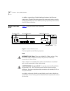
Connecting
Equipment to the
Console Port
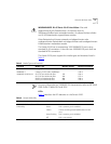
Connection to the console port is used for direct local management. The
Switch 9100 console port settings are set as follows:
■
Baud rate
— 9600
■
Data bits
— 8
■
Stop bit
— 1
■
Parity
— None
■
Flow control
— XON/XOFF
The terminal connected to the console port on the switch must be
configured with the same settings. This procedure will be described in the
documentation supplied with the terminal.
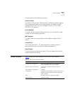
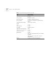
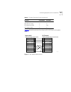
Appropriate cables are available from your local supplier. To make your
own cables, pinouts for a DB-9 male console connector are described in
Ta ble 6
.
Table 6
Console Connector Pinouts
Function Pin Number Direction
DCD (data carrier detect) 1 In
RXD (receive data) 2 In
TXD (transmit data) 3 Out
DTR (data terminal ready) 4 Out
(continued) (continued)