


30
C
HAPTER
2: I
NSTALLATION
AND
S
ETUP
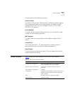
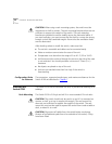
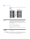
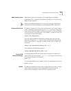
Figure 6 shows the pin-outs for a 9-pin to 9-pin PC-AT serial null modem
cable.
Figure 6
PC-AT serial cable pin-outs
Powering-up the
Switch
The Switch 9100 contains two power supplies. When both are
connected, the power supplies operate in a load-sharing configuration. If
one power supply fails, the other power supply takes over, ensuring
uninterrupted network operation. Either one, or both power supplies may
be connected to power the switch. It is recommended that you connect
both power supplies.
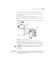
To power-up the switch, follow these steps:
1
Connect one or both power cables to the switch.
2
Connect the power cable(s) to the wall outlet(s).
The switch automatically powers-up once it has been connected to the
wall outlet.
Checking the
Installation
After turning on power to the Switch 9100, the device performs a
Power
On Self-Test
(POST).
Power On Self-Test
(POST)
During the POST, all ports are temporarily disabled, the packet LED is off,
the power LED is on, and the MGMT LED flashes green. The MGMT LED
flashes until the switch has successfully passed the POST.
Screen
DTR
TxD
RxD
CTS
Ground
DSR
RTS
DCD
Cable connector: 9-pin female
Switch 9100
Cable connector: 9-pin female
PC-AT Serial Port
Screen
DCD
RxD
TxD
DTR
Ground
DSR
RTS
CTS
Shell
4
3
2
8
5
6
7
1
Shell
1
2
3
4
5
6
7
8
91_ser2