


Installing the Motherboard
User’s Manual
2-9
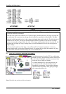
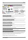
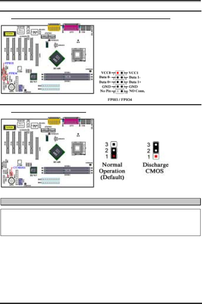
(6). FPIO3 (USB 3/4) and FPIO4 (USB 5/6) Headers: Additional USB Plugs Header
These headers are for connecting the additional USB
port plugs. Each connector can provide two
additional USB plugs for a total of four additional
USB plugs. You can use the special USB port
expansion cable to connect it (the cable come with
the metal plate can fixed on the back panel of
computer chassis). It can provide total of four
additional USB plugs.
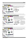
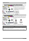
(7). CCMOS1: CMOS Discharge Jumper
Jumper CCMOS1 discharge CMOS memory. When
you install the motherboard, make sure this jumper is
set for normal operation (pin 1 and 2 shorted). See
Figure 2-7.
Figure 2-7. CCMOS1 jumper setting
Note
Before you clear the CMOS, you have to first turn the power off (including the +5V standby power).
Otherwise, your system may work abnormally.
After updating your BIOS and before boot up, please clear the CMOS first. Then put the jumper to its
default position. After that, you can reboot your system and ensure that your system is working fine.