


Chapter 3
SD7-533 Motherboard
3-18
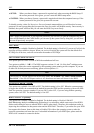
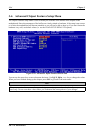
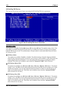
SIS OnChip IDE Device:
This item can let you sets several items concerning the SIS OnChip IDE device parameters.
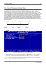
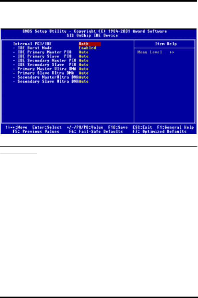
Figure 3-6B. SIS OnChip IDE Device Screen Shot
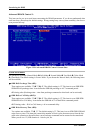
Internal PCI/IDE:
Four options are available: Disabled ) Primary ) Secondary ) Both. The default setting is Both. This
item allows you disable all internal PCI/IDE devices, or enable one of them. Of course you can enable
both PCI/IDE devices as well. The enabled items will apear white in color and disabled items will show
in a blue green color.
"
IDE Burst Mode:
Two options are available: Disabled or Enabled. The default setting is Enabled. Selecting Enabled
reduces latency between each drive read/write cycle, but may cause instability in IDE subsystems that
cannot support such fast performance. If you are getting disk drive errors, try setting this value to
Disabled. This field is not available to enter when the “Internal PCI/IDE” field is Disabled.
"
IDE Primary Master PIO:
Six options are available: Auto ) Mode 0 ) Mode 1 ) Mode 2 )Mode 3 ) Mode 4. The default
setting is Auto. The BIOS can auto-detect the transfer mode of the IDE devices in order to set its data
transfer rate (Default). You can select the PIO mode from Mode 0 to Mode 4 of the IDE devices in
order to set its data transfer rate. This field is not available to enter when the “Internal PCI/IDE”
field is Disabled or Secondary.
"
IDE Primary Slave PIO:
Six options are available: Auto ) Mode 0 ) Mode 1 ) Mode 2 )Mode 3 ) Mode 4. The default
setting is Auto. The BIOS can auto-detect the transfer mode of the IDE devices in order to set its data
transfer rate (Default). You can select the PIO mode from Mode 0 to Mode 4 of the IDE devices in
order to set its data transfer rate. This field is not available to enter when the “Internal PCI/IDE”
field is Disabled or Secondary.