


Chapter 2
SD7-533 Motherboard
2-14
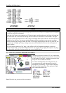
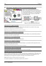
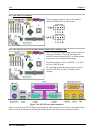
(13). CD1 and AUX1 Headers
These connectors connect to the audio output of
internal CD-ROM drive or add-on card.
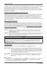
(14). SW1 and D15: Processor Default Setting Switch and 5V Standby LED
SW1 is a processor default setting switch, used to set
and test in our factory. Please do not change the
small DIP switchs setting on SW1, as wrong settings
may prevent your computer from booting.
The default setting of SW1 is: DIP SW 1, 3, 5 and 6
are set to “ON” position.
D15 will light up after the power switch is pressed,
this LED will show you the 5V standby power
situation.
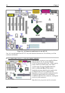
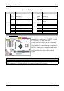
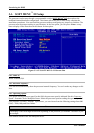
Figure 2-10. SD7-533 back panel connectors
Figure 2-10 shows the SD7-533 back panel connectors. These connectors are used for connecting outside
devices to the motherboard. We will describe which devices will attach to these connectors below.