


Installing the Motherboard
User’s Manual
2-11
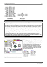
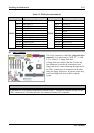
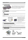
Table 2-2. FPIO1 pin count name list
PIN Name Significance of signal PIN Name Significance of signal
PIN 1 HDD LED (+) PIN 2 SP-LED (+)
PIN 3 HDD LED (-) PIN 4 SP-LED (-)
PIN 5 Reset SW (-) PIN 6 PWR-ON (+)
PIN 7 Reset SW (+) PIN 8 PWR-ON (-)
PIN 9 No Connection PIN 10
No Pin
PIN 11 No Pin PIN 12 No Pin
PIN 13 No Pin PIN 14 No Pin
PIN 15 Speaker (+5V) PIN 16 PWR LED (+)
PIN 17 Speaker (GND) PIN 18 No Pin
PIN 19 Speaker (GND) PIN 20 PWR LED (-)
PIN 21 Speaker (Driver) PIN 22 No Connection
FPIO1
PIN 23 No Pin
FPIO1
PIN 24 No Connection
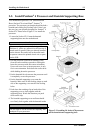
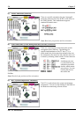
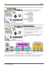
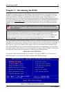
(9). FDC1 Connector
This 34-pin connector is called the “floppy disk drive
connector”. You can connect a 720K, 3.5’’, 1.44M,
3.5” or 2.88M, 3.5” floppy disk drive.
A floppy disk drive ribbon cable has 34 wires and
two connectors to provide the connection of two
floppy disk drives. After connecting the single end to
the FDC1, connect the two connectors on the other
end to the floppy disk drives. In general, people only
install one floppy disk drive on their computer
system.
Note
A red mark on a wire typically designates the location of pin 1. You need to align the wire pin 1 to the
FDC1 connector pin 1, and then insert the wire connector into the FDC1 connector.