


Chapter 3 43
External Module Disassembly Process
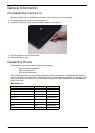
IMPORTANT:The outside housing and color may vary from the mass produced model.
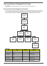
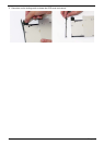
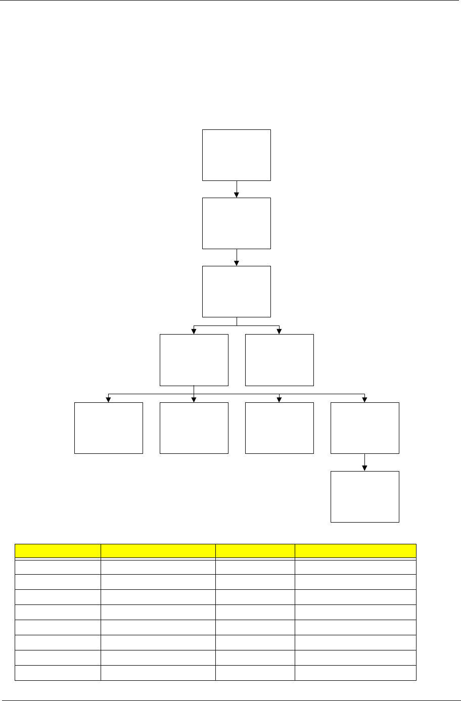
External Modules Disassembly Flowchart
The flowchart below gives you a graphic representation on the entire disassembly sequence and instructs you
on the components that need to be removed during servicing. For example, if you want to remove the main
board, you must first remove the keyboard, then disassemble the inside assembly frame in that order.
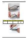
Screw List
Step Screw Quantity Part No.
Memory Cover M2.5*10 4 86.N2702.003
HDD Cover M2.5*10 2 86.N2702.003
ODD Module M2*3 1 86.N2702.007
ODD Bracket M2*2.5 3 86.N2702.005
WLAN Module M2*3 2 86.N2702.007
HDD Carrier M3*3 4 86.N2702.006
CPU Fan M2.5*10 2 86.N2702.003
Thermal Module CPU_SCREW_SPRIN 4 86.N2702.008
Disconnect power
and signal cables
from system
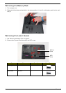
Remove
Battery
Turn off system
and peripherals
power
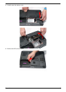
Remove
DIMMs
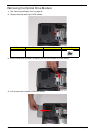
Remove
WLAN
Remove
HDD
Remove
ODD
Remove
Lower Covers
Remove
CPU Fan
Remove
Thermal Module