


157
Introduction
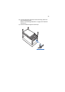
The system supports installation of up to four memory boards to the
mainboard. Memory boards connect to the mainboard through the x16
PCI Express slots or memory board slots A, B, C, and D (refer to
“Mainboard” on page 17 for the location of the memoy board slot).
The memory board is equipped with four DIMM slots that support two
DDR2 channels, with two DIMMs installed per channel (DIMM 1A or 1B
or DIMM 2A or 2B). Each DIMM slot supports 512 MB, 1 GB, 2 GB or 4
GB DDR2-400 MHz (PC2-3200) registered ECC memory modules.
Important: DDR2 DIMM modules on each memory board must be
installed in pairs. Each pair is referred to as a bank. A bank may
consist of one rank (a pair of single-channel DIMMs) or two ranks (
a pair of dual-channel DIMMs).
When using dual-channel memory mode, use the same type and
size DDR2 DIMM modules and follow the “DIMM module
population order” on page 159 to ensure that you get dual-
channel memory performance.
The memory boards can be configured in a redundant or non-
redundant configuration. Memory boards configured using RAID or
mirroring are in redundant configuration. If a memory board that is
configured in a redundant configuration has a DIMM or memory board
fault, the memory board and/or DIMM containing the fault can be
removed and replaced while the system is powered on (See page 51 for
detailed instructions on how to hot-remove and hot-replace memory
boards). Memory boards that are configured in a non-redundant
configuration (including memory boards configured with spare
memory) must not be removed while the system is powered on (Refer
to page 69 for detailed instructions on how to remove and replace
memory boards.).