


51
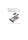
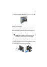
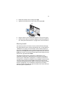
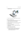
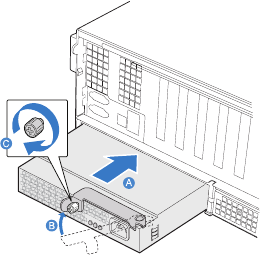
4 Rotate the handle to the closed position (B).
5 Tighten the thumbscrew to secure the power supply (C).
6 Plug the power cord into the DC receptacle on the power supply.
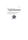
7 Verify that the LEDs on the power supply are functioning. Refer to
the “Rear panel LED indicators” on page 14 for more information.
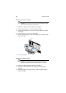
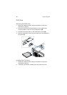
Memory board
The memory boards in the server connect to the mainboard through
the x16 PCI Express slots or memory board slots A, B, C, and D. Refer to
“Mainboard” on page 17 for the location of the memory board slot.
Up to four memory boards can be installed in the server. Each memory
board has four DIMM slots that support two DDR2 channels, with two
DIMMs per channel. The memory boards support both single-rank and
double-rank, registered ECC DIMMs.
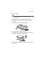
The memory boards can be configured in a redundant or non-
redundant configuration. Memory boards configured using RAID or
mirroring are in redundant configuration. If a memory board that is
configured in a redundant configuration has a DIMM or memory board
fault, the memory board and/or DIMM containing the fault can be
removed and replaced while the system is powered on. Memory boards
that are configured in a non-redundant configuration (including
memory boards configured with spare memory) must not be removed
while the system is powered on.