


1 System tour
18
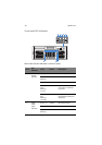
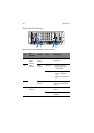
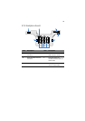
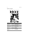
* Reserved for remote management of server. This requires installation of an ARMC/3 (Acer
remote management card/3)
D PCI-X 100MHz (Slot 6) T Power distribution board
(PDB) signal connector
E Hot-plug PCI Express x8
(with x4 throughput) –
(Slot 5)
U CPU socket 1
F Hot-plug PCI Express x8
(with x4 throughput) –
(Slot 4)
V CPU socket 2
G Hot-plug PCI Express x8
(with x4 throughput) –
(Slot 3)
W CPU socket 4
H Hot-plug PCI-X 133MHz –
(Slot 2)
X VRM 10.2 connector (CPU 4)
I Hot-plug PCI Express x8 –
(Slot 1)
Y CPU socket 3
J Gigabit LAN 1 (top),
LAN 2 (bottom)
Z SCSI connector channel A
(connects to the SCSI
backplane board)
K Dual USB 2.0 ports AA VRM 10.2 connector (CPU 3)
L Serial (top),
VGA port (bottom)
BB Integrated SCSI hardware
RAID BBU connector
M Memory board slot A CC SCSI connector channel B
(for internal or external SCSI
connector)
N RTC battery DD Integrated SCSI hardware
RAID cache memory (DDR-2)
slot
O SATA connector EE Memory board slot D
P Front panel board
connector
FF Memory board slot C
Item Description Item Description