Getting Started
2 – 4 • • • • • • • • • • • • • • • • • • • • • • • • • • • • • • • • • • • • • • • • • • • • • • • • • • • • • • • •
2
the dashboard on the driver side of the vehicle. If the DLC is not located under
the dashboard as stated, a decal describing its location should be attached to
the dashboard in the area the DLC should have been located.
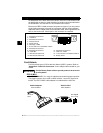
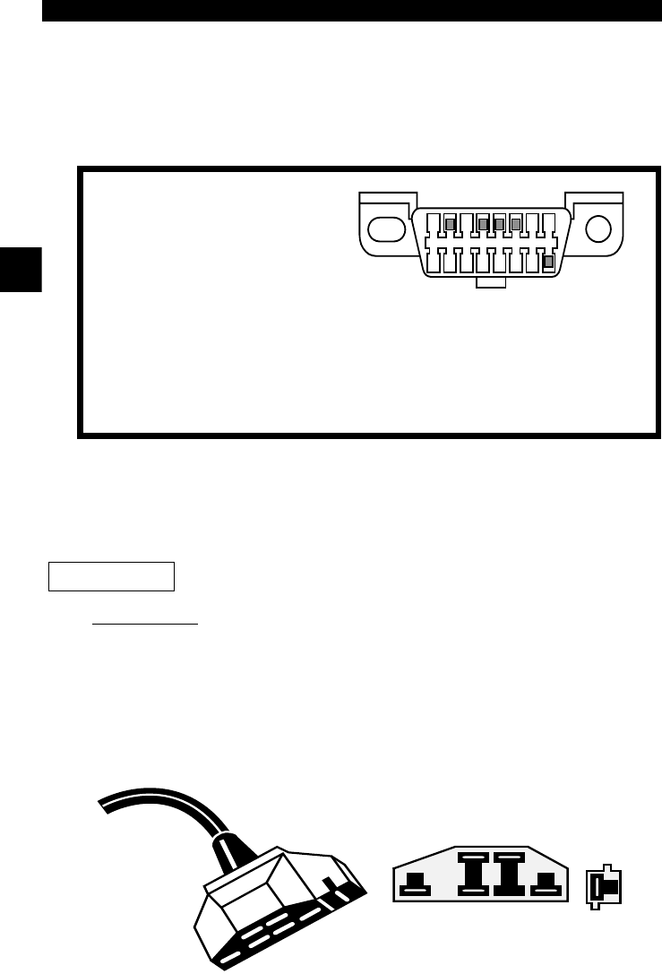
Because the OBD II J1962 connector has power and ground, you only need a
single cable connection to the tool for both power and tool communications.
Attach the OBD II adapter cable to the extender cable, both supplied with the
tool, to connect the tool. Certain pins in the connector are reserved.
Ford Historic
Ford used three types of DLCs with their historic (OBD I) systems. Refer to
“Appendix A - Data Link Connectors" for the adapter cable needed for your
vehicle.
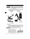
Use the Battery Power cable to provide power to the scan tool
for all systems.
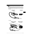
EEC-IV/MCU
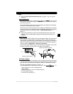
The EEC-IV/MCU DLC is a large six-sided connector with a pigtail connector.
The pigtail connector is not used on MCU vehicles – leave the pigtail unat-
tached. The EEC-IV/MCU cable adapter is included with the scan tool.
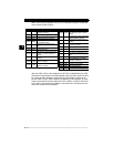
1 - Manufacturer Reserved
2 - J1850 Bus+
3 - Manufacturer Reserved
4 - Chassis Ground
5 - Signal Ground
6 - CAN High, J-2284
7 - K Line, ISO 9141-2 & ISO/DIS 14230-4
8 - Manufacturer Reserved
9 - Manufacturer Reserved
10 - J1850 Bus
11 - Manufacturer Reserved
12 - Manufacturer Reserved
13 - Manufacturer Reserved
14 - CAN Low, J-2284
15 - L Line, ISO 9141-2 & ISO/DIS 14230-4
16 - Battery Power
1
9
8
16
IMPORTANT
Vehicle DLC
EEC-IV/MCU
Cable Adapter
EEC-IV/MCU
STI Pigtail
EEC-IV
only
To Scan
Tool


