


Overview 700-701-100-02
4 August 9, 2002 UTU-701 and ETU-751 List 1
FRONT AND REAR PANEL COMPONENTS
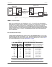
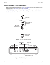
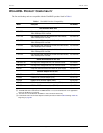
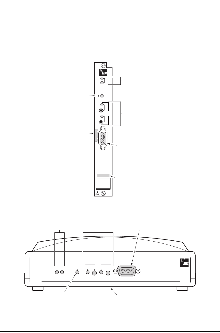
The line and desktop unit front panels are shown in Figure 2 and Figure 3, respectively. The components on these
panels are described in Table 3 on page 5 and in Table 4 on page 6.
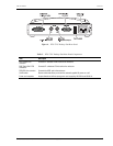
The ETU-751C desktop unit rear panel is shown in Figure 4 on page 7. The components on this panel are
described in Table 5 on page 7. The pinouts for the desktop unit rear panel connectors are listed in Table 34 and
Table 35 on page 64.
Figure 2. UTU-701C Line Unit Front Panel
Figure 3. ETU-751C Desktop Unit Front Panel
UTU-701
V.24 (RS-232) console port
Warranty control
number label
Bar code label
(located on circuit
side of line card)
I/F ALM LED
HDSL LEDs
Loopback LEDs and
push buttons
LPBK
LOC
REM
I/F
SYNC
ALM
ALM
HDSL
G.703
V.24
WorldDSL
HDSL LEDs
Loopback LEDs
and push buttons
V.24 (RS-232)
console port
HDSL
SYNC
ALM
HDSL
I/F
LOC
LPBK
REM
ALM
Unit ID and bar code labels
(located on bottom of unit)
ALM LEDI/F
G.703