


700-701-100-02 Overview
UTU-701 and ETU-751 List 1 August 9, 2002 5
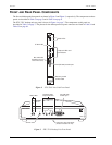
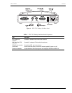
Table 3. Line and Desktop Unit Front Panel Components
Name Function
HDSL SYNC LED Displays synchronization state for the HDSL loop.
HDSL ALM LED Displays alarm state for the HDSL loop.
I/F ALM LED Displays alarm state for the G.703 data port.
LOC LPBK LED Displays local (LOC) loopback state.
LOC LPBK Button Activates the local HDSL analog loopback.
REM LPBK LED Displays remote (REM) loopback state.
REM LPBK Button Activates the remote interface loopback.
V.24 (RS-232) console
port
Provides bi-directional communication between the unit and an external maintenance terminal through
a V.24 (RS-232C) interface to allow configuration and performance monitoring through the console
screen menus as described in “System Configuration” on page 25. This connector can also be used to
download new firmware to the line unit’s flash memory as described in “Firmware Download Utility” on
page 62. This port is configured as DCE (see “Maintenance Terminal Connection” on page 25 for
pinouts).
Bar code label (all units) Contains the serial number and part number of the unit, as indicated in both bar code and text format.
Also contains the configuration number of the unit, as indicated by "CFG: Rnn," where nn is the
configuration number. For example, CFG: R07 would indicate configuration number 07.
Warranty control
number label (UTU-701C)
Indicates the beginning year and month of the line card warranty. Also indicates the line card revision
number. For example, a warranty control number of "803R07" would indicate a warranty beginning in
the year 1998 (8), during the month of March (03), and line card revision number R07.
Unit ID label (ETU-751C) Identifies the model number, manufacturer, part number, and input voltage range of the ETU. Includes
the CE mark, certifying that the unit is in compliance with directive EN300 386-2. See “Certification and
Warranty” on the inside of the back cover.