


Reference Information 700-701-100-02
64 August 9, 2002 UTU-701 and ETU-751 List 1
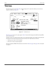
REFERENCE INFORMATION
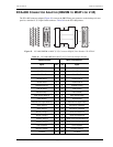
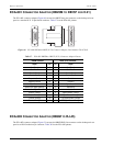
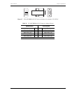
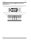
This section lists the pinouts for the ETU-751C rear panel connectors and the ECA-80x connector adapters.
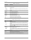
ETU-751C CONNECTOR PINOUTS
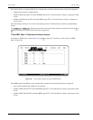
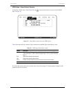
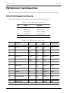
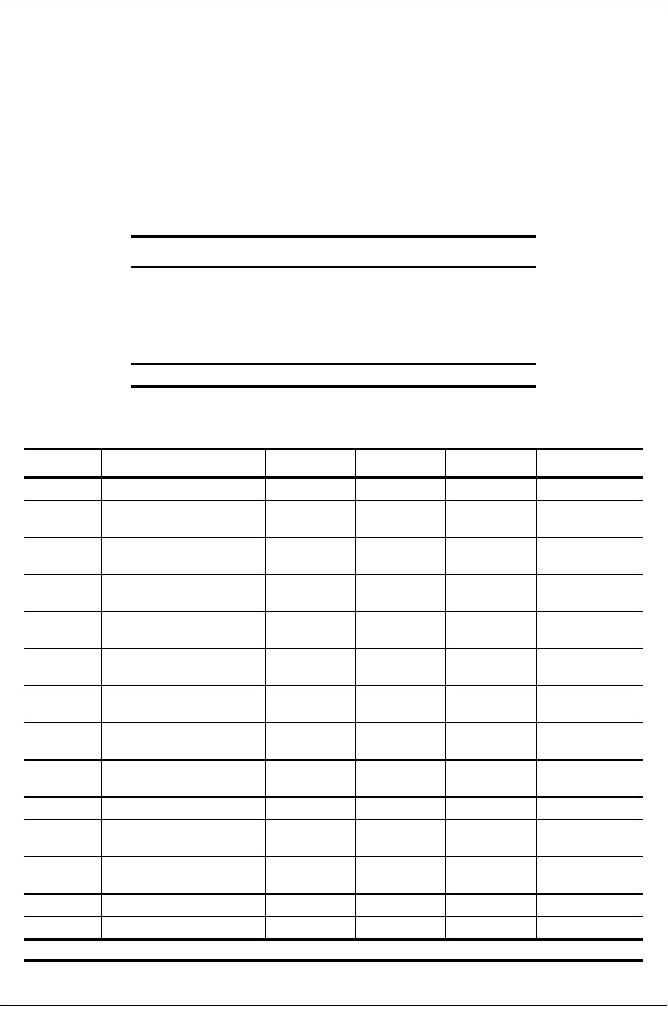
The pinouts for the ETU-751C rear panel connectors are listed in Table 34 and Table 35.
Table 34. D9F HDSL Line Connector Pinouts
Pin
(a)
Signal Description
4 HDSL_RING_A HDSL Loop 1 (Ring)
9 HDSL_TIP_A HDSL Loop 1 (Tip)
1 HDSL_RING_B HDSL Loop 2 (Ring)
6 HDSL_TIP_B HDSL Loop 2 (Tip)
(a) All other pins are not used. Pins 1 and 6 not used on single-pair HDSL cards.
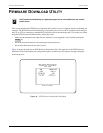
Table 35. D25F Data Port Connector Pinouts
Pin
(a)
Signal Name V.35 V.36 X.21 DCE Input/Output
7 Signal Ground SG SG SG
2
14
Send Data SD_A
SD_B
SD_A
SD_B
T_A
T_B
Input
3
16
Receive Data RD_A
RD_B
RD_A
RD_B
R_A
R_B
Output
15
12
Send Timing SCT_A
SCT_B
ST_A
ST_B
S_A
S_B
Output
17
9
Receive Timing RCT_A
RCT_B
RT_A
RT_B
not used Output
24
11
Terminal Timing SCTE_A
SCTE_B
TT_A
TT_B
TT_A
TT_B
Input
5
13
Clear to Send CTS CTS not used Output
6
22
Data Set Ready DSR DSR not used Output
8
10
Received Line Signal Detect RLSD RLSD I_A
I_B
Output
25 Test Mode TM TM not used Output
4
19
Request to Send RTS RTS C_A
C_B
Input
20
23
Data Terminal Ready DTR DTR not used Input
18 Local Loopback LL LL not used Input
21 Remote Loopback RL RL not used Input
(a) All other pins are not used.