


System Configuration 700-701-100-02
26 August 9, 2002 UTU-701 and ETU-751 List 1
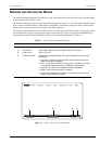
To connect and configure a maintenance terminal:
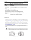
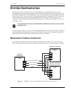
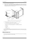
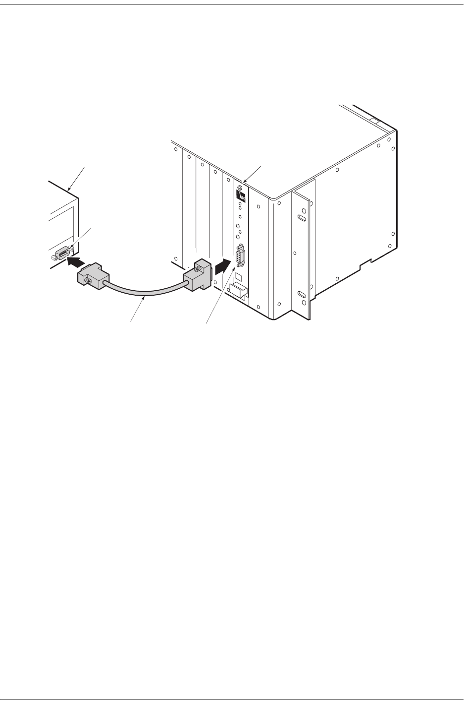
1 Connect a serial cable from the maintenance terminal 9-pin COM port to the line or desktop unit console port
connector (Figure 11). Ensure the Data Terminal Ready (DTR) signal from the terminal is connected as the
HDSL card will not communicate without it. Data Terminal Ready (DTR) may also be asserted by connecting
the DSR output signal (pin 6) to the DTR input (pin 4).
Figure 11. Connecting a Maintenance Terminal to a Line Unit
2 Configure the maintenance terminal for the following communication settings:
• VT100 Emulation or ANSI (if VT100 is not available)
• Clear the modem initialization string, if supported by the terminal
• Bits per second: 1200, 2400, 4800, 9600 (default), or 19200 bps (recommended)
• Data bits: 8
• Parity: None
• Stop bits: 1
• Flow Control: None
If using a PC and Microsoft Windows terminal emulation program, deselect Show Scroll Bars and Use Function,
Arrow, and Ctrl Keys from the Settings Terminal Preferences menu in Windows 3.1 or from the Properties menu
in Windows 95.
MODEM CONNECTION
For remote access to the line unit, an auto-answer modem can be connected to the console port. Use a null modem
cable to connect the WorldDSL line unit and the modem.
PairGain
Maintenance terminal
Line unit
Interface cable
Console port
9-pin COM port