ATLAS 550 System Manual Section 2, Engineering Guidelines
61200305L1-1F © 2002 ADTRAN, Inc. 27
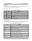
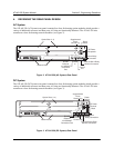
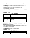
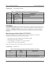
Option Module LEDs Displays (by row) the operational condition of each module installed in the
option slots. (See Table 3 on page 27.) All LEDs will be off if no option
module is installed.
Status Indicates the operational condition of modules installed in the option slots.
Online Indicates whether the module is available for use or is currently in use. If
the module is manually taken offline, this LED is turned off.
Test Indicates that one or more ports within a module are in test.
ACO Switch Clears the Alarm Relay connection located on the rear panel of the ATLAS
550.
CRAFT Port Allows the ATLAS 550 to connect to a computer or modem using the
CRAFT port (an RJ-45 port).
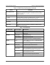
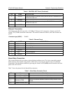
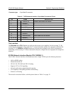
Table 3. ATLAS 550 LEDs
For these LEDs... This color light... Indicates that...
Power Green the unit is on.
Off the unit is off.
Ethernet Green (solid) the physical link is up.
Green (flashing) there is activity on the LAN.
Off the physical link is down - no Ethernet connection.
Remote Yellow a user is logged in the system via CONTROL/CRAFT
port or via Ethernet.
Off there are no users logged into the system.
System Green (solid) no diagnosed system faults were found.
Green (fast blink) a flash download is in progress.
Yellow (solid) a fault was diagnosed, but the condition no longer exists.
The condition will be recorded in the system log.
Red (solid) an error condition with either the power supply or the
system temperature is present.
Red (fast blink) a fatal error occurred during flash download.
Off power is not currently supplied to the system.
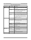
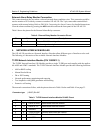
Table 2. ATLAS 550 Front Panel Description (Continued)
Feature Description


