


Installation Procedures: Exchange Side Panels
InfraStruXure System—Installation and Start-Up 21
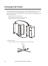
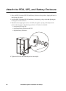
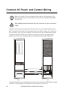
2. Remove the solid side panels from the sides of the UPS that will be adjacent to the PDU and the
Battery Enclosure in your planned configuration.
3. Remove the side panels from the sides of the PDU and Battery Enclosure that will not be
adjacent to the UPS.
4. Remove the rear hole covers from the panels that you removed in step 3.
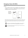
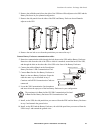
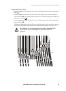
Connect Battery Enclosure communication cables:
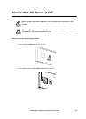
5. Route the communication cable through the hole between the UPS and the Battery Enclosure.
Route the cable from the side of the UPS to which it is attached, around the back of the UPS,
and through the hole on the other side of the UPS to the front of the Battery Enclosure.
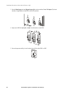
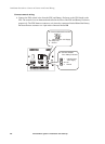
6. Connect the cable to Port 1 on the first adjacent
Battery Enclosure’s XR Communication Card.
7. Connect Port 2 on the first Battery Enclosure to
Port 1 on the next Battery Enclosure. Route the
cable the same way as described in step 5.
Continue until all XR Communication Cards are
connected.
8. Locate the XR Communication Card terminator
and insert it into the open port of the last Battery Enclosure in your configuration.
9. Install, on the UPS, the side panels that you removed from the PDU and the Battery Enclosure
in step 3 and reattach the ground wires.
10. Install, on the PDU and the Battery Enclosure, the solid side panel that you removed from the
UPS in step 2 and reattach the ground wires.
Note
The terminator is in Port 1 of the UPS XR Communication Card and
in Port 2 of the Battery Enclosure XR Communication Card.
XR Communications Card
Port 1
Port 2
XR Communications Card
Port 1
Port 2
XR Communications Card
Port 1
Port 2
Symmetra PX UPS
XR Battery Enclosure 1
XR Battery Enclosure 2
Te r mina t or
C
o
m
m
.
C
a
b
l
e
C
o
m
m
.
C
a
b
l
e