


InfraStruXure System—Installation and Start-Up 33
Connect an Emergency Power Off Switch
Overview
Connecting the switch. Choose one of the
following methods to connect a switch to the
EPO interface:
• Contact closure
• 24 VDC
•24 VAC
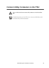
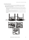
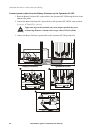
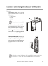
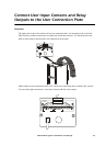
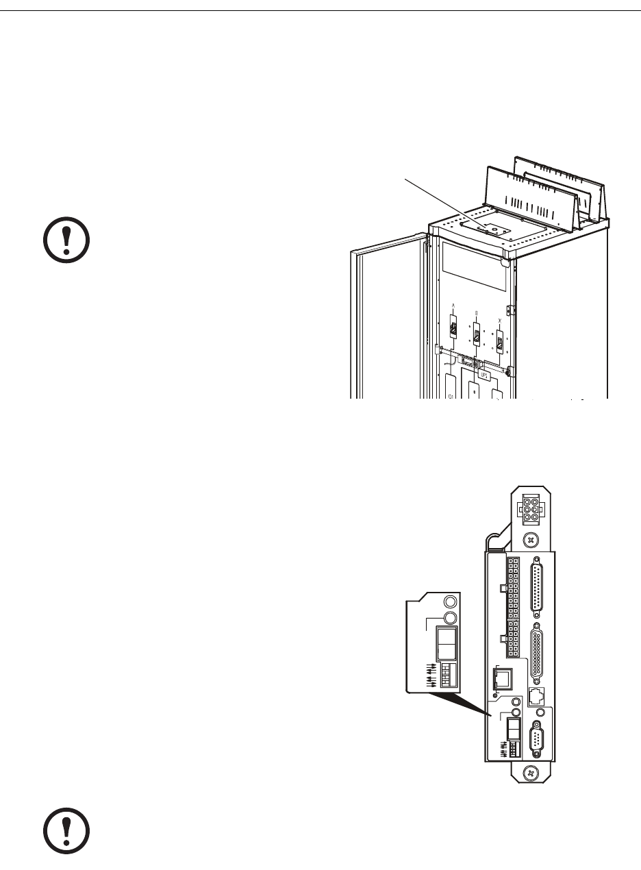
The EPO connections are made at the PDU
user connection plate. The figure to the right
shows the location of the user connection
plate. It is mounted on the roof of the PDU
enclosure (
) and connections are made from
inside the PDU. Use the knockout in the plate
to run wires out the roof of the PDU.
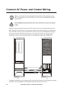
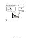
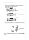
Configuring and testing. Configuring and
testing of the switch is done through the EPO
interface on the PDU monitoring unit. The
figure to the right shows the PDU monitoring
unit and the location of the EPO LEDs and
switches.
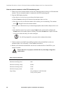
Note
Contact closure is recommended.
Note
APC offers an optional InfraStruXure EPO System (EPW9). Contact your APC sales
representative, or visit the APC Web site (www.apc.com) for more information.
NO NC
USER / EPO CONTACTSTO UPS
DISPLAY
10=G RN
100=ORN
NETWORK
POWER
RS-232
CONSOLE PORT
9600-8-N-1
RESET
TRIPPED
STATUS
LINK RX/TX
ARMED
TEST
EPO
885-2288
12345678910111213
25242322 2120 191817 161514
NO
NC
TRIPPED
ARMED
TEST
EPO