


11
3.1 RS-232 SERIAL INPUT
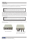
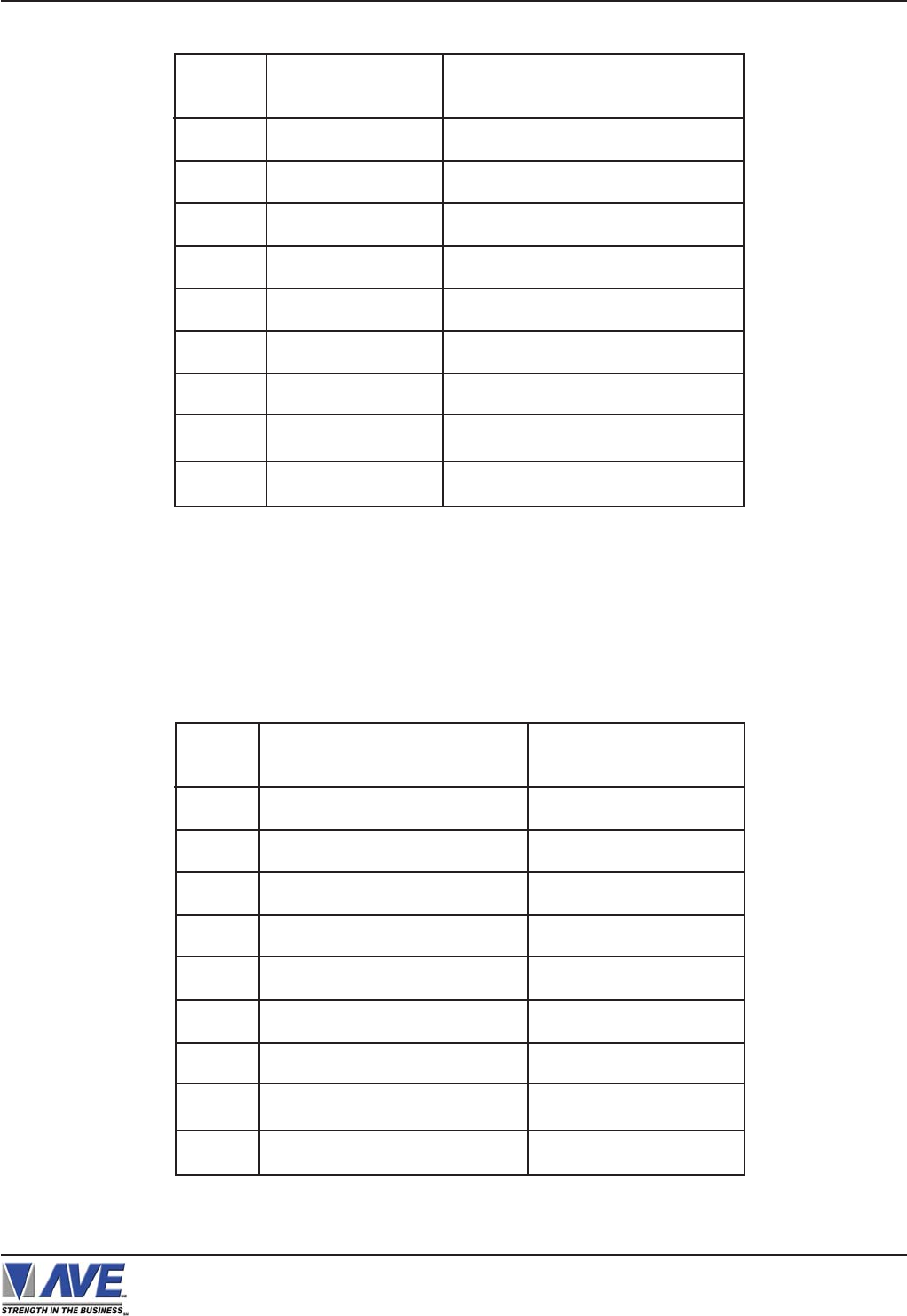
The VSI-Pro accepts serial data via the DB-9 female connector located on the rear of VSI-Pro. This connector is
similar to “AT” type computer RS232 serial ports and the pin out is identical. Table 1 shows the standard pin out for
VSI-Pro RS-232 female connector. On the other hand Table 2 compares the VSI-Pro RS-232 with standard “AT”
computer’s RS-232 connector.
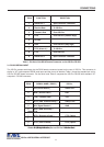
Table 2: RS-232 DB-9 Pin-Out vs VSI-Pro DB-9 Pin-Out
Table 1: Pin-Out of the DB-9 Female Connector on the VSI-Pro RS-232
1 Alarm Out 1 Open Collector Transisitor
2 Receive Data To VSI-Pro
3 Transmit Data From VSI-Pro
4 DTR From VSI-Pro (Remain High)
5 Ground
6 DSR From VSI-Pro (Stay High)
7 RTS ( Alarm In ) To VSI-Pro
8 CTS From VSI-Pro
9 Alarm Out 2 Open Collector Transistor
PIN #
FUNCTION
DIRECTION
1 CD (Carrier Detect ) Alarm Out 1
2 RxD ( Recieve Data ) RxD
3 TxD ( Transmit Data ) TxD
4 DTR ( Data Terminal Ready ) Aways True
5 SG ( Signal Control ) GND
6 DSR ( Data Set Ready )
Aways True
7 RTS ( Request to Send ) CTS ( Option
)
8 CTS ( Clear to Send ) RTS ( Option
)
9 RI ( Ring Indicator ) Alarm Out 2
PIN # SIGNAL NAME ( RS232 ) VSI-Pro
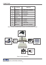
VSI-Pro VIDEO SERIAL INTERFACE
CONNECTIONS