


AMX 68000 Target Guide
K
A
DAK
39
5.2 Custom Clock Driver
The easiest way to create a custom clock driver is by example. Assume that the
counter/timer which you intend to use for your AMX clock is characterized as follows:
The I/O base address of the clock is at 0xFFA00100.
The clock interrupt is generated using vector number 25.
The clock interrupt is dismissed by writing bit pattern 0x08 to the clock register at its
base address plus 4.
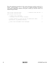
The Interrupt Handler for an assembly language conforming clock ISP for such a device
could be coded as follows:
XDEF _clockih
_clockih EQU *
*
* receives D1 = ISP root parameter = A(clock base)
*
MOVEA.L D1,A0 * A0 = A(clock base)
MOVE.B #$08,4(A0) * Dismiss interrupt
RTS * Return
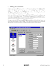
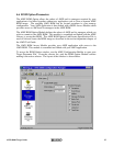
Create a clock ISP root for the clock as described in Chapter 4.3. Use the following
parameters in your definition of the clock ISP.
ISP Type: Clock Handler
ISP Root: clockroot
Interrupt Handler: clockih
Handler Language: Assembly
Parameter Type: Value
Parameter: 0xFFA00100
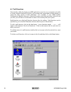
Note that you could just as easily create a fast clock ISP root for this simple clock as
described in Chapter 4.4 avoiding the need to create the Interrupt Handler clockih. Use
the following parameters in your definition of the fast clock ISP.
ISP Type: Fast Clock Handler
ISP Root: clockroot
Address #1: 0xFFA00104
Value #1: 0x08
I/O Delay: leave blank
Address #2: leave blank
Value #2: leave blank
Write Size: 8-bit