


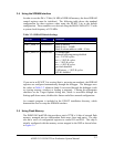
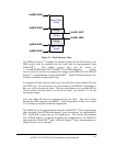
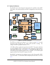
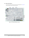
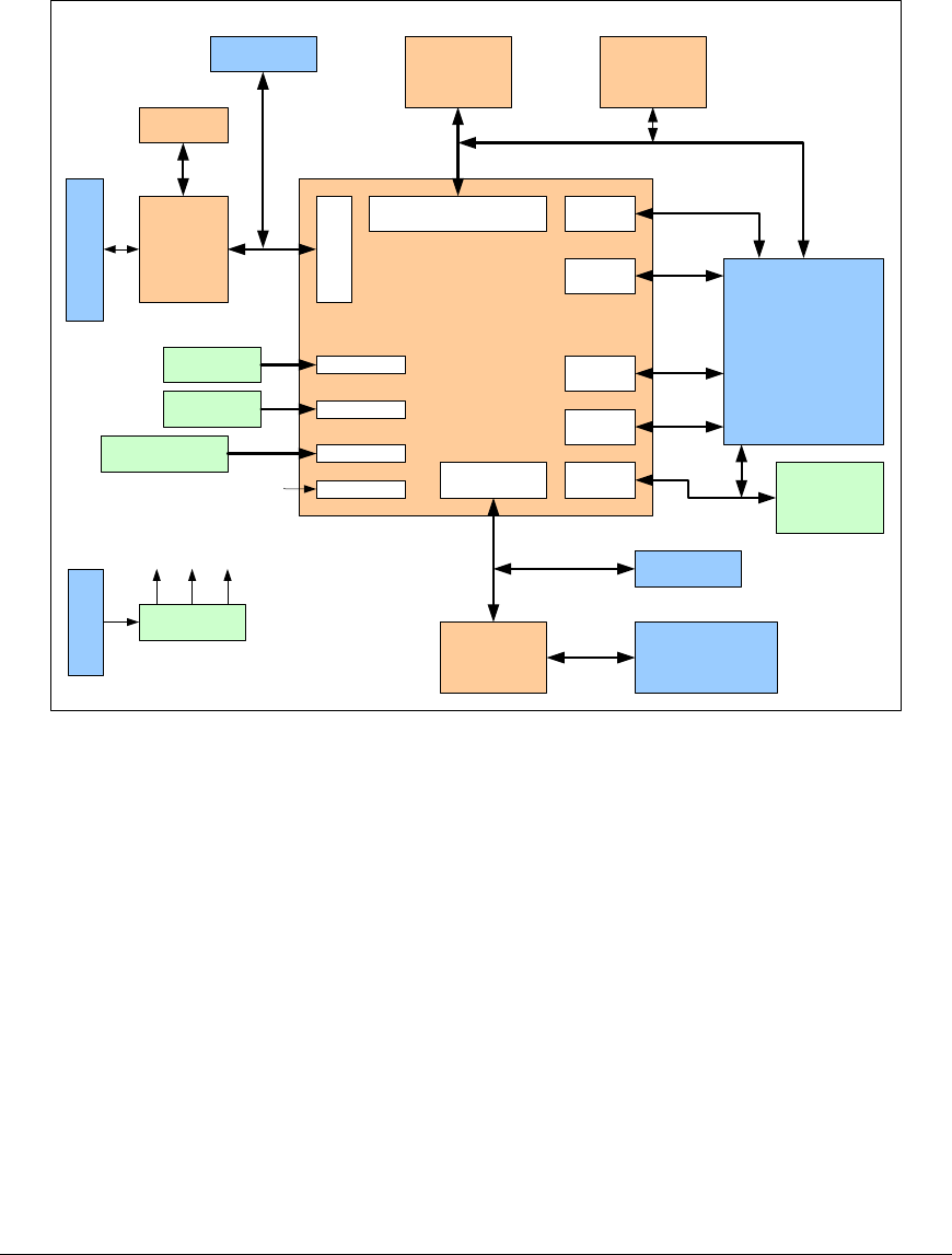
4.2 System Architecture
The EZ-KIT Lite has been designed to demonstrate the capabilities of the ADSP-
21535 DSP. This section describes the DSP’s configuration on the EZ-KIT Lite
board.
ADSP-21535
DSP
(U1)
SPORT0
Connector
AD1885
Codec
(U7)
Stereo LINEIN/
MIC and
LINEOUT
Connectors
SRAM
USB Connector
EZ USB FX
JTAG Header
Expansion
Connectors
(P1, P2, P3)
Power
Regulation
LEDs, PBs
and Clock
Logic
External Bus Interface
Unit
PF15:0SPORT0
SPORT1
JTAG Port
VDD_INT
VDD_EXT
5V
+7.5V
Connector
A5V 3.3V
3.3V
20MHz
Oscillator
CLK_IN
UART1:0
Timer2:0
SPI 1:0
USB
4M X 32bit
SDRAM
(U5, U6)
Power
Management
32.768KHz
Crystal
RTC
544KB Flash
(U4)
Figure 4-1: System Architecture
The DSP has a default core voltage of 1.5V. Refer to section 3.6.1 for more
information about changing the core voltage while the DSP is running. The
voltage of the DSP’s peripheral interface is 3.3V.
A 20 MHz oscillator supplies the input clock to the DSP. The speed at which the
core and peripherals operate is determined by the configuration of the multiplier
select switch (SW2) at reset. (See section 4.3.4.) By default, the DSP core runs
at 300 MHz and the peripheral interface runs at 120 MHz. A 32.768 kHz crystal
supplies the Real Time Clock (RTC) inputs of the DSP
The EZ-KIT Lite board can be configured to boot in all of the possible ADSP-
21535 boot modes. For information about configuring the boot mode, see section
4.3.3.
ADSP-21535 EZ-KIT Lite Evaluation System Manual
4-2