


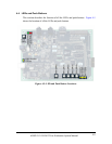
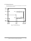
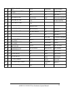
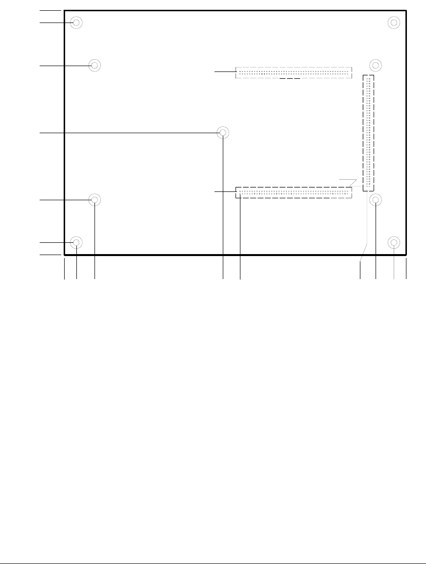
4.6.3 Mechanical Dimensions
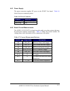
The following figure shows the location of the mounting holes as well as the PIN1
of each of the expansion connectors.
P1
P3
P2
0.000
0.000
0.250
0.250
1.125
3.875
4.750
5.000
0.625
1.300
3.750
2.500
3.250
3.600
6.375
6.750
1.400
6.200
7.000
Figure 4-7: Mechanical Drawing
ADSP-21535 EZ-KIT Lite Evaluation System Manual
4-1