


LIST OF TABLES
Table 1-1: Related DSP Documents ................................................................................1-5
Table 1-2: Related VisualDSP++ Documents .................................................................1-5
Table 2-1: Minimum PC Configuration...........................................................................2-2
Table 3-1: EZ-KIT Lite Evaluation Board Memory Map ...............................................3-2
Table 3-2: SDRAM Default Settings...............................................................................3-3
Table 3-3: Programmable Flag Pin Summary .................................................................3-5
Table 3-4: Power Management PF Settings.....................................................................3-6
Table 4-1: Connector Interfaces.......................................................................................4-4
Table 4-2: Boot Mode Select Switch (SW1) Settings .....................................................4-6
Table 4-3: PLL Setup Switch (SW2) Functions ..............................................................4-7
Table 4-4: Programmable Flag LEDs..............................................................................4-9
Table 4-5: Programmable Flag Switches.......................................................................4-10
Table 4-6: Power Connector..........................................................................................4-15
Table 4-7: Current Measurement Resistors ...................................................................4-15
LIST OF FIGURES
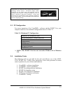
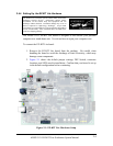
Figure 2-1: EZ-KIT Lite Hardware Setup .......................................................................2-4
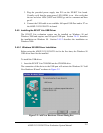
Figure 2-2: Add New Hardware Wizard Dialog Box ......................................................2-5
Figure 2-3: Search for the driver......................................................................................2-6
Figure 2-4: Search the CD-ROM.....................................................................................2-6
Figure 2-5: The driver is located......................................................................................2-7
Figure 2-6: Search for .sys File Dialog Box ....................................................................2-7
Figure 2-7: Open the .sys File..........................................................................................2-8
Figure 2-8: Copying Files................................................................................................2-8
Figure 2-9: Finish the Software Installation ....................................................................2-9
Figure 2-10: Found New Hardware Wizard ..................................................................2-10
Figure 2-11: Search for a Suitable Driver......................................................................2-11
Figure 2-12: Locate Driver Files....................................................................................2-12
Figure 2-13: Driver File Search Results .......................................................................2-13
Figure 2-14: Completing Driver Installation Dialog Box..............................................2-14
Figure 2-15: New Session Dialog Box ..........................................................................2-15
Figure 3-1: Flash Memory Map.......................................................................................3-4
Figure 4-1: System Architecture......................................................................................4-2
Figure 4-2: Jumper Locations..........................................................................................4-5
Figure 4-3: Audio Input Jumper Settings (JP1)...............................................................4-6
Figure 4-4: Default PLL Setup Switch Settings (SW2)...................................................4-7
Figure 4-5: LED and Push Button Locations...................................................................4-8
Figure 4-6: Connector Locations ...................................................................................4-11
Figure 4-7: Mechanical Drawing.....................................................................................4-1
ADSP-21535 EZ-KIT Lite Evaluation System Manual
vi