


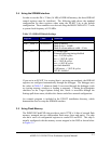
4.3 Jumper and DIP Switch Settings
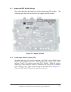
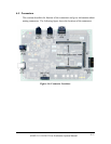
This section describes the function of all the jumpers and DIP switches. The
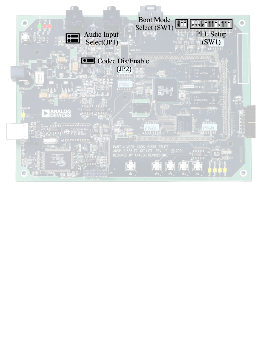
following figure shows the location of all the jumpers and DIP switches.
Figure 4-2: Jumper Locations
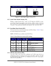
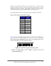
4.3.1 Audio Input Select Jumper (JP1)
The audio input jack (P5) can be connected to the MIC1 or the LINEIN input
channels of the AD1885 Codec (U7). When the JP1 jumpers connect pins 1 and 3
and pins 2 and 4, P3 connects to the mono MIC1 channel. When the jumpers
connect pins 3 and 5 and pins 4 and 6, P5 connects to the stereo LINE_IN channel
of the AD1885 Codec. These jumper settings are illustrated below in Figure 4-3.
(The words MIC and LINE are on the board as a reference)
ADSP-21535 EZ-KIT Lite Evaluation System Manual
4-5