


During reset, the function of these pins is to setup the PLL. At this time, these
signals are attached to the PLL setup switch (SW2) and determine the core and
external clock speeds of the DSP. Approximately 120uS after reset has been de-
asserted these pins are no longer attached to SW2, but function as PFs.
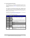
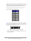
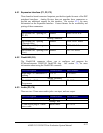
The following table shows the switch position that corresponds to a DSP pin.
Table 4-3: PLL Setup Switch (SW2) Functions
DSP Pin Switch
Position
MSEL0
1
MSEL1 2
MSEL2 3
MSEL3 4
MSEL4 5
MSEL5 6
MSEL6 7
DF 8
SSEL0 9
SSEL1 10
None 11
Bypass 12
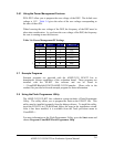
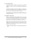
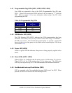
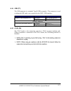
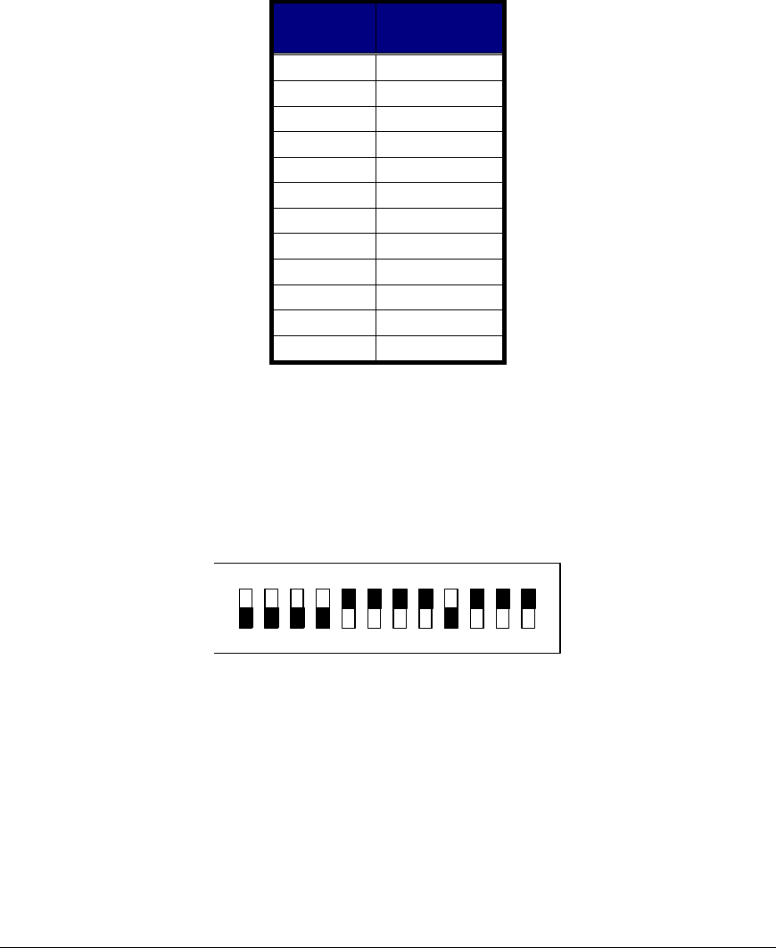
Figure 4-4 shows the default setting for SW2. This will produce a 300MHz core
clock speed and a 120 MHz peripheral interface speed. For more information
about setting up the multiplication factors, refer to the Managing DSP Clocks
section of the
ADSP-21535 DSP Hardware Reference.
1 2 345678910 11 12
ON
Figure 4-4: Default PLL Setup Switch Settings (SW2)
! NOTE: A switch setting of “ON” supplies a logic low (0) on the
corresponding DSP pin.
ADSP-21535 EZ-KIT Lite Evaluation System Manual
4-7