


INDEX
A
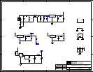
architecture.........................................4-2
audio.................................................4-12
B
boot mode select ................................4-6
C
connectors ........................................4-11
P1,P2,P3................................4-3, 4-12
P10 ...............................................4-14
P4 ..........................................3-3, 4-12
P5 .................................. 4-3, 4-5, 4-12
P6 ..........................................4-3, 4-12
P7 .................................................4-13
P8 .................................................4-13
P8 ...................................................4-4
P9 ..........................................4-3, 4-14
power management........................3-6
contents ..............................................2-1
core voltage........................................4-2
current measurements ......................4-15
customer support................................1-3
D
documents ..........................................1-4
E
example programs..............................3-6
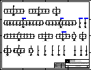
External Bus Interface Unit ...............4-3
F
features...............................................1-1
flash memory .............3-2, 3-3, 4-3, 4-12
Flash Programmer Utility ..................3-6
H
Help, online........................................1-4
I
installation...................................2-2, 2-9
verification...................................2-14
Windows 2000 USB Driver.........2-10
Windows 98 USB Driver...............2-5
interfaces
audio............................... See SPORT0
expansion .... See connectors:P1,P2,P3
JTAG...................................See JTAG
IO voltage...........................................4-2
J
JTAG.........................................4-4, 4-13
jumpers...............................................4-5
default settings ...............................2-4
JP1................................... 4-3, 4-5, 4-6
JP2...........................................4-3, 4-6
L
LEDs ................................... 3-5, 4-1, 4-8
LED1..............................................4-9
LED2..............................................4-9
LED3..............................................4-9
LED4..............................................4-9
LED5........................... 2-14, 2-15, 4-9
LED6.......................................2-5, 4-9
LED7.......................................2-5, 4-9
LED8.......................................2-5, 4-9
M
memory map ......................................3-2
N
NMI....................................................4-9
P
PC configuration................................2-2
Phase Lock Loop (PLL)..............4-2, 4-6
power connector...............................4-14
Programmable Flags ...................3-5, 4-6
LEDs ..............................................4-9
PF14-PF12 .....................................3-6
push buttons .................................4-10
push buttons .........4-8.
See also switches
R
Real Time Clock (RTC).....................4-2
reset....................................................4-9
board ............................................4-10
DSP ................................................4-9
restrictions..........................................3-2
ADSP-21535 EZ-KIT Lite Evaluation System Manual
1