


4.4.1 Programmable Flag LEDs (LED1, LED2, LED3, LED4)
Four LEDs are connected to four of the DSP’s Programmable Flag (PF) pins,
PF0-3. These LEDs are active HIGH and are lit by an output of “1” from the
DSP. Refer to section 3.6 for more information about using of the PFs when
programming the DSP.
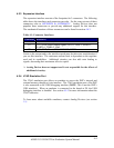
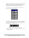
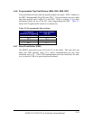
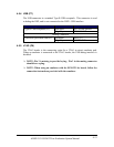
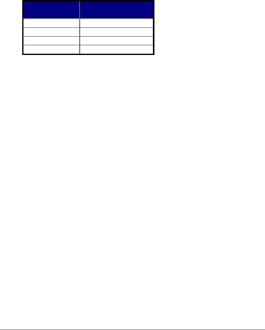
Table 4-4: Programmable Flag LEDs
LED Reference
Designator
DSP Programmable
Flag Pin
LED4 PF0
LED1 PF1
LED2 PF2
LED3 PF3
4.4.2 USB Monitor LED (LED5)
The USB Monitor LED (LED5) indicates that USB communication has been
initialized successfully and you may connect to the DSP using a VisualDSP++
EZ-KIT Lite session. This should take approximately 15 seconds. If the LED
does not light, try cycling power on the board and/or reinstalling the USB driver
(see section 2.4.5).
4.4.3 Power LED (LED6)
LED6 is a green LED that indicates when power is being properly supplied to the
board.
4.4.4 Reset LEDs (LED7, LED8)
When LED8 is lit, it indicates that the master reset of all the major ICs is active.
When LED7 is lit, the USB interface chip (U11) is being reset. The USB chips
will only reset on power-up, or if USB communication has not been initialized.
4.4.5 Non-Maskable Interrupt Push Button (SW3)
SW3 is connected to the Non-maskable Interrupt (NMI) pin of the DSP. When
pressed, the DSP will vector to the NMI interrupt vector.
ADSP-21535 EZ-KIT Lite Evaluation System Manual
4-9