


User Manual version 2305
APOLLO 120/150 III
4-30
4 2 1
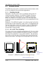
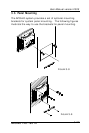
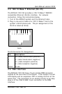
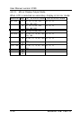
FIGURE 4-1
The I/O interfaces located at the rear side of the chassis are
used to connect external peripheral devices, such as a mouse,
a keyboard, a monitor, serial devices or parallel printer…etc.
Before any connection, make sure that the computer and the
peripheral devices are turned off.
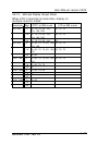
4.1. Parallel Port
The APOLLO 120/150 can support the latest EPP and ECP
parallel port protocols. It can be used to connect to a wide
array of printers, ZIP drive, parallel scanner and any other
parallel devices. The printer interface on the APOLLO
120/150 III is a 25-pin female D-SUB connector. To connect
any parallel device, follow the steps below:
1. Turn off the system and the parallel devices.
2. Plug in the male connector of the parallel device to the
25-pin female D-SUB connector and fasten the retaining
screws.
3. Turn on the system and the attached parallel devices.
4. Refer to the parallel device’s manual for instruction to
configure the operation environment to recognize the new
attached devices.
5. You may need to run the CMOS setup to change the
hardware device setup.