


User Manual version 2305
APOLLO 120/150 III
5-
73
ÅK¥ó«á»\
APOLLO ÅK¥ó«á»\²Õ«~
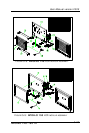
I/O »\
MODULE APOLLO IO A1.0
SCSI 68P-SCSI 68P L:180mm
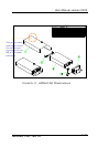
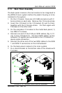
FIGURE 5-12: APOLLO BACK MODULE ASSEMBLY
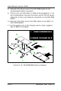
5.12. Back Panel Assembly
The back panel module is the last module to be integrated to
the APOLLO main system before the plastic housing is to be
installed to the system.
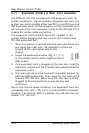
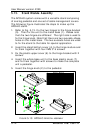
1. On the I/O board, there are 6 D-SUB connectors with 2
bronze sticks on each side. Remove the 12 bronze sticks.
2. Insert the I/O board to the I/O bracket (2) and fix them
together with the 12 bronze sticks. Fix them again with
2 screws on the other side.
3. Fix the complete I/O module to the metal back panel (1)
five FMS 3*5 screws.
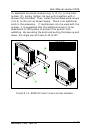
4. Connect one end of the 2 68-pin SCSI cables (Fig. 5-12
(4)) to the I/O board (3). Via the 2 SCSI cables, all the
onboard I/O signals are converted to the I/O board for
device cable connection.
5. Connect the other end of the two SCSI cables to the SCSI
1 and SCSI 2 connectors on the motherboard.
6. Fix the back panel module to the main system.
7. Fix a stand bracket at the bottom side of the chassis with
2 screws.