


User Manual version 2305
APOLLO 120/150 III
5-
74
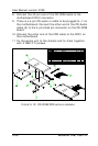
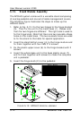
©³®yÅKªO
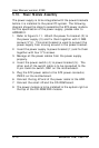
APOLLO °ò®y¼Ò²Õ
HINGE (¥ª) with LOCK
HINGE (¥k)
APOLLO 120/150 Âà¶b-×¹¢¤U»\
APOLLO 120/150 ¶ì½¦©³®y
Âà¶b¤ä¬[
APOLLO 120/150 Âà¶b-×¹¢¤W»\
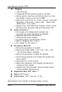
FIGURE 5-13: APOLLO PEDESTAL ASSEMBLY
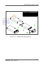
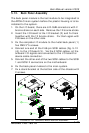
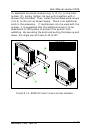
5.13. Stand Module Assembly
The APOLLO system comes with a versatile stand composing
of one big pedestal and one set of cable management covers.
The following figure illustrates the steps to make up the
APOLLO stand.
1. Refer to Fig. 5-13. Fix the two hinges to the hinge bracket
(5). Then fix the unit to the metal base (1). Please note
that the two hinges are different. The right side is used to
fix the hinge knob. Note that there are two avocado-shape
holes on the metal base. The two avocado holes are used
to fix the stand to the table for special application.
2. Insert the stand bottom cover (4) to the hinge module and
fix them together with four FMS 3*6 screws.
3. Fix the plastic upper cover (6) to the hinge bracket with 2
screws.
4. Insert the whole base unit to the base plastic cover (7)
and fix them together with screws to make the complete
unit a pedestal.
5. Insert the hinge knob (2) to the pedestal.