


User Manual version 2305
APOLLO 120/150 III
5-
62
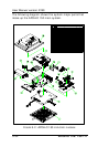
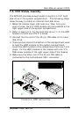
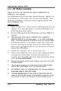
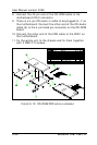
5.8. LCD Module Assembly
Figure 5-8 and 5-9 illustrate the way to assemble the
APOLLO’s LCD module.
The LCD does not fix to the main system directly. Rather, it is
to be fixed to a LCD holder, then to the main system. The
assembly of APOLLO 120 LCD module slightly differs from
that of APOLLO 150.
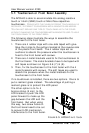
APOLLO 120
1. Refer to Figure 5-8. There are two LCD brackets (2) & (3)
used to fix to the LCD panel (1) to the LCD holder (11)
from the up & down sides.
2. Fix the LCD panel to the LCD holder with four PMS 3*8
screws.
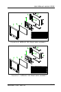
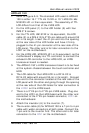
3. The standard LCD used in APOLLO 120 is SANYO
MXS121022010 or its equivalent. It is a TTL interface
LCD. The LCD cable (4) is a DF9-41S to 2*25-pin cable
with around 35 cm in its length. Insert the 41-pin end
into the opening at the rear side of the LCD holder and
have it firmly plugged to the 41-pin connector at the rear
side of the LCD panel.
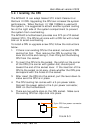
4. Attach the insulator (10) to the invertor (9).
5. The invertor cable (8) is a 4-pin to 4-pin cable with wafer
connectors at both sides. Connect the one end to
invertor first. The other end is for later connection to the
INV1 on the motherboard.
6. Connect the pink-white high voltage wires from the LCD
to the invertor.
7. The invertor module is to be fixed at the right middle
side of the LCD holder with the up side down.
8. For APOLLO 120, the IR/LED board (2) is to be fixed to
the lower side of the LCD holder.
9. The two speakers are to be fixed to the right and left
sides of the IR/LED board. The speaker wires are to be
connected to the 2-pin header on the IR/LED board.