


User Manual version 2305
APOLLO 120/150 III
5-
64
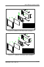
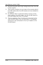
10. Connect the pink-white high voltage wires from the LCD
to the invertor.
11. The invertor module is to be fixed at the reverse side of
the LCD holder after the LCD module is to be installed to
the system.
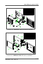
12. For APOLLO 150, fix 6 bronze sticks (15 mm) to the
lower sides of the LCD holder. Fix the IR/LED board to
the LCD holder with two 3*6 screws.
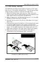
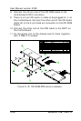
13. The two speakers (Fig. 5-8 (6)) are to be fixed to the
right and left sides of the IR/LED board. The speaker
wires are to be connected to the 2-pin header on the
IR/LED board.