


User Manual version 2305
APOLLO 120/150 III
4-33
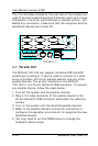
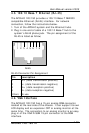
4.3. 100/10 Base-T Ethernet (RJ-45)
The APOLLO 120/150 provides a 100/10 Base-T NE2000
compatible Ethernet (RJ-45) interface. For network
connection, follow the instructions below.
1. Turn of the APOLLO system and the Ethernet hubs.
2. Plug in one end of cable of a 100/10 Base-T hub to the
system’s RJ-45 phone jack. The pin assignment of the
RJ-45 is listed as follow;
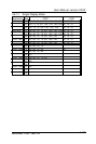
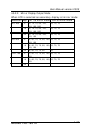
RJ-45 Connector Pin Assignment
Pin Description
1
2
3
6
others
Tx+ (data transmission positive)
Tx- (data transmission negative)
Rx+ (data reception positive)
Rx- (data reception negative)
No use
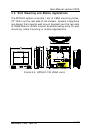
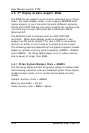
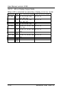
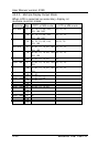
4.4. VGA Interface
The APOLLO 120/150 has a 15-pin analog RGB connector
located at the rear side of the chassis. It can support its own
LCD display and an expansion CRT or analog monitor at the
same time. The connection to an analog monitor is an easy
plug-in of the VGA D-SUB 15-pin connector to the RGB
interface.
1
2 3 4 5 6 7
8
RJ-45