


User Manual version 2305
APOLLO 120/150 III
5-
72
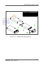
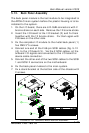
5.11. Expansion Outlets & Riser Card Assembly
The APOLLO 120/150 provides PCI/ISA expansion slots for
system expansion. Via the specially designed riser card, the
system can accommodate either two PCI or one PCI plus one
ISA expansion cards; all the connectors of the expansion card
will come out from the expansion outlet on the left side of the
chassis for further cable connection.
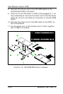
The expansion outlet bracket has to be installed to the
system before plugging the riser card to the motherboard
PCI/ISA expansion slot.
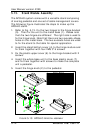
1. When the system is reverse with the rear side facing you
and lower side near you, the expansion outlets are
located at the right upper side of the
chassis.
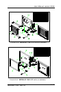
2. Install the expansion window (Fig. 5-1 (11))
to the chassis and fix them together with 2
FMS screws.
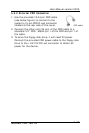
3. If no expansion card is plugged to the riser card, seal the
expansion outlets with the 2 metal slips located inside the
expansion outlet.
4. The riser card (8) is to be fixed with the metal bracket (9)
with two FMS screws first. Then, plug the riser card to the
onboard PCI/ISA slot. Make sure the riser card is firmly
plugged to the motherboard to prevent any bad
connection.
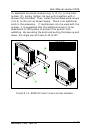
Due to the internal space limitation, the expansion card can
not exceed 190*120 (L*W) mm if no internal FDD is installed.
However if an internal FDD is installed, the ISA card can not
exceed 170*120 mm.