


User Manual version 2305
APOLLO 120/150 III
5-
70
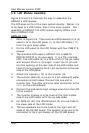
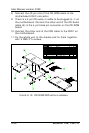
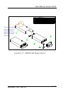
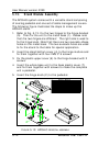
5.10. Power Module Assembly
The power supply is to be integrated with the power brackets
before it is installed to the panel PC system. The following
diagram shows the steps to assemble the ATX power module.
For the specification of the power supply, please refer to
APPENDIX.
1. Refer to Figure 5-11. Attach the power fix bracket (2) to
the power supply (3) and fix them together with 2 FMS
screws (3*5). This small bracket is used to prevent the
power supply from moving around in the power bracket.
2. Insert the power supply to power bracket (1) and fix them
together with four 3*5 screws.
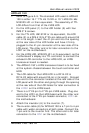
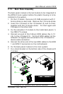
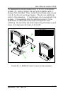
3. Manage all the power cables from the power supply
properly.
4. Insert the power switch (4) to power bracket (5). The
other end of the switch cable is to be connected to the
2-pin POWER ON switch, SW1 on the motherboard.
5. Plug the ATX power cable to the ATX power connector,
PWR 3 on the motherboard.
6. Connect the big 4P end of the power cable to the HDD.
7. Connect the small 4P end the CD-ROM board.
8. The power module is to be installed to the system right on
the top of the CD-ROM/FDD module.