


User Manual version 2305
APOLLO 120/150 III
5-
66
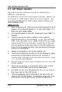
After finishing the LCD module installation, the module is to
be assembled to the front bezel module, then to the chassis
with the motherboard and touch controller already on.
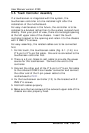
1. Use special air blower to blow any dust between the LCD
and touchscreen before the two modules are assembled
together. Retain the LCD module and the front bezel
module together with 8 FMS 3*6 screws.
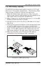
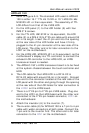
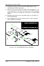
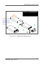
2. Install the whole front bezel module with LCD already on
to the system chassis with the motherboard, touchscreen
controller and HDD module already on.
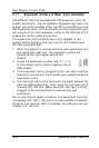
3. The LCD cable is already at the rear side of the LCD holder
through the cutout. Make sure the other end is to go
through the rectangle opening at the rear side of the
system chassis and have it connected to LCD connector,
LCD1 on the motherboard.
SPECIAL ATTENTION NEEDS TO BE PAID WHEN PLUGGING THE LVDS OR
LCD CABLE TO THE LCD HEADER CONNECTOR ON THE MOTHERBOARD.
MAKE SURE PIN 1 OF THE ONBOARD LCD CONNECTOR MATCH PIN 1 OF
THE CABLE. ANY WRONG PLUGGING OR SHIFTED PLUGGING WILL
DAMAGE THE LCD PANEL OR LEAD TO MAL-FUNCTION.
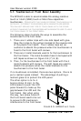
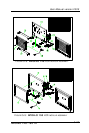
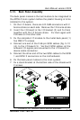
4. The touchscreen 5-pin flat cable should go through the
rectangle opening at the left side of the LCD holder, then
get into the chassis from the oval-shape cutout at the left
side of the chassis. Connect this cable to the touchcreen
controller. Connect the other end of the touch power cable
to the onboard PWR 1.
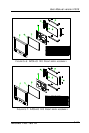
5. For APOLLO 150, the invertor now is to be fixed to the left
outward side of the chassis and have the invertor cable go
into the chassis through the cutout. Connect the other
end of the invertor cable to the motherboard’s INV1.
6. Connect the other end of the IR/LED cable to the IR/LED
board.